Well , last time we saw what went wrong , or at least what didn’t go as expected , now I have to find a way to fix it. I’ll start on focusing on the issue of making the doors lock and unlock. I think I should make a new module for high voltage and high amperage needed by the doors. I’ll call it DCU (Door Control Unit). My design constraints for this should be on one side dictated by my existing module on the other side by the existing car circuit. The original circuit I made only had 2 signals coming out at 12V. The time the signal stays high on these lines can be changed by code. This makes my inputs for the DCU have the following constraints:
- 12V signal input
- High to actuate
- 2 lines one for lock one for unlock
Now for the part that came from the factory. I wrongly assumed I could send the signals into the car computer that would control the actuators. My new solution is to just control the actuators directly bypassing any of the car’s computer systems. This should reduce my chance of failure this time round :). This looks like a good solution because the main actuator ( aka driver’s door actuator) has a feedback circuit that tells the computer it’s been locked manually so the computer can lock and unlock the other doors by just locking his door (a feature that makes my circuit a bit redundant but I’ve never let that stop me).
The actuators are 12V and the fuse for them in the car’s fuse holder is 20 amps. That means I have to make a motor control unit that can handle at least 30 amps (safety margin). The controller should have 2 12V inputs that allow me to set the motor polarity one way or another ( the 2 input lines i talked about earlier.
Because I can set the length of the signal I want to have the actuator …actuating… while the input signal is high. This could be done with an H bridge and some relays ( cheapest solution ). And it could be connected into the car like this :
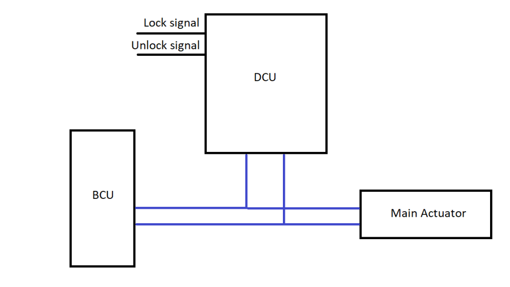
This would seem sufficient for the application but what happens if I am trying to have the actuator go one way (ordered by the DCU) and the car for whatever reason wants to go the other (ordered by the MCU)? I have one supply wire of the connected to 12V by my circuit and ground by the car BCU… even worse the other wire is connected to ground by my circuit and to 12V by the same BCU. I get not one, but two short circuits and probably 4 doors that don’t lock or unlock electrically … if i get lucky and don’t blow the BCU completely. To avoid the chance of this happening I need to somehow disconnect the BCU from doing anything to the actuator while my new control circuit is doing stuff. My only option here is to disconnect the 2 power wires that go to the actuator and run the actuator how I want making it go one way or another. When I am finished I can simply have the circuit switch control from my circuit back to the BCU again. So I need to add these 2 disconnects relays and have the DCU in between the BCU and actuators:
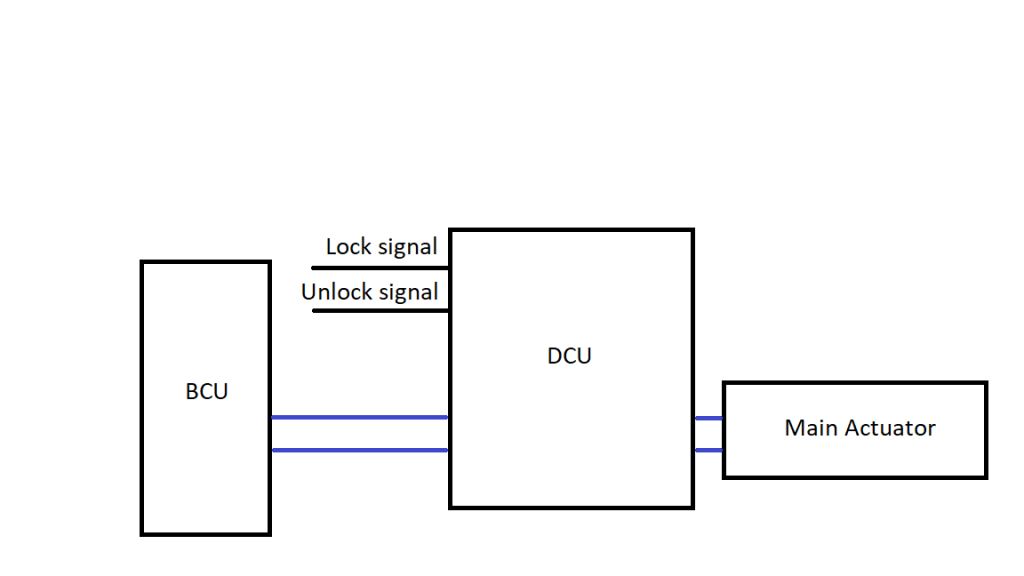
This 2 relays need to trigger first then the ones in the H bridge. This means I need some kind of delay …and knowing that the disconnect worked first would be a nice safety feature. This means some kind of delay circuit and a way to check that the disconnect worked beforehand. I can have the disconnect be 1 single relay with 3 internal switches , 2 of them for the power lines to the actuator and a third to get a confirmation signal that switching happened. I could have the delay and checking done by another microcontroller but that would mean having a 5V line and more expensive parts. The cheap option would be an analog circuit. A 555 timer chip should to the job outside goes through the diodes and nicely:
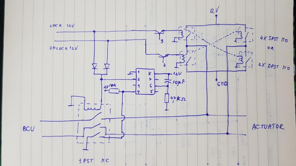
So now the signal comes from the signal lines the diodes protect against it going back the other way. This signal is used to trigger the decoupling relay and trigger the 555 IC. Triggering the relay also opens the path to ground of the 555’s RESET pin. The 555 is configured as a delay so after a little time it turns on the other 2 transistors which allow the inputs to control the H bridge. This got complicated fast but it’s better than the extra parts to have a microcontroller controlling everything.