In my Arduino-based-car-radio-steering-wheel-interface-thing I talked a lot about infrared communications (IR communications) but without going into great detail about it.
Infrared light is light transmitted at frequencies low enough that the human eye can’t see. This became especially useful to the mass consumer market when TV sets became widespread. The first televisions only had a few buttons on the front to adjust the channel and sound volume. Once the electronics industry became mature enough and the consumer demanded more comfort, the idea of controlling the TV set remotely appeared. At first the primitive “remotes” where nothing more than control boxes that where connected to the TV via a cable. Soon enough the idea of controlling the TV without being tethered to it caught traction so TV remotes started using light as a communications method. This had 2 disadvantages: it was light in the visible spectrum so any source of light could accidentally send signals to the TV and because of this and other technical limitations the user had to aim the remote very precisely at the receiving sensor. This problem where dealt with by using infrared light. There are much fewer sources of infrared light in the house so the problem of false signals was eliminated. Also, because humans can’t see infrared light this meant the beam of light could be as powerful as technology permitted, enabling control from further and further away. Once this technology was perfected it became ubiquitous and therefore cheap. You can find televisions, air conditioning units, stereos (even some for automotive use) led light strips even small remote-controlled power plugs that are controlled by infrared remote.
An IR communication path is made of 2 parts: the emitter (an infrared LED) and a receiver. The led is tied to a microcontroller and the chip simply has to turn the designated pin on and off in a pattern specific to the IR communications protocol that is wanted and that’s it. On the receiver side a designated pin receives a sequence of pulses from the sensor witch itself is a simple detection device. IR sensors usually have only 3 pins, 2 relegated to power and one on witch they output the transcoded signal. All the receiving logic is done by the attached microcontroller. And in our case the thing that makes a microcontroller understand IR protocols and communicate with them is the software library. The LED being turned on and off is a form of amplitude modulation at a fixed frequency, the details of which are dependent on exactly who developed the protocol that is being used. Thankfully all this is irrelevant because it is taken care of by the software library. As long as we have the emitter or the receiver (even both in some cases) the library makes it easy to send or receive signals in a number of common protocols.
All the information that is necessary to use the library can be found on the library’s git page, that being said here’s an example to get started.
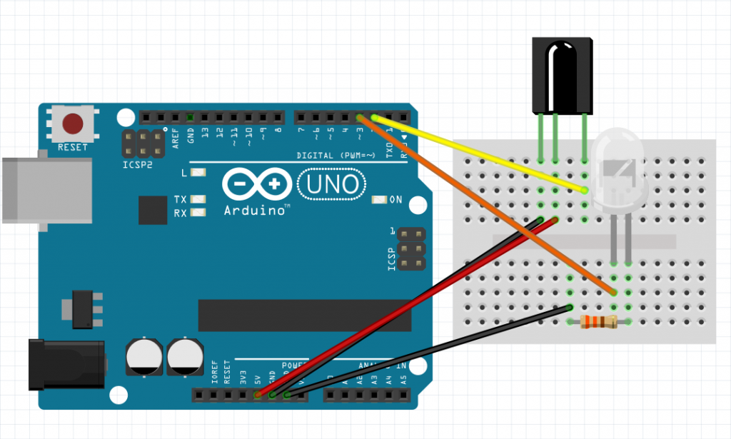
To use the library all you need is an Arduino board configured like I used it in developing my project. We have the IR receiver (an TSOP382) connected to pin 2 and a transmitter LED tied through a resistor to pin 3. It is important to note that in the library pin 3 is hardcoded as the sender pin so this can not be changed. From a software point of view, we first need to declare the use of the library like this:
#include <IRLibSendBase.h>
and the libraries we need (just the SONY protocol here):
#include <IRLib_P02_Sony.h>
We combine all of it:
#include <IRLibCombo.h>
and initialize it:
IRsend mySender;
All of this gives us the sender object for pin 3.
Now for the receiver:
IRrecvPCI myReceiver(2);
Yes it’s that simple. But we also need to decode the signal so we need a decodes object just like we needed a sender and receiver:
IRdecode myDecoder;
Oh, and in the setup you need to start the receiver:
myReceiver.enableIRIn();
Don’t worry all this code is pretty much standard. All you will ever change is the protocols you want to use for the sender and that is it. Now let’s do something with it.
You can read data from the receiver by checking if there’s any data to read and the decoding it:
  if (myReceiver.getResults()) {
    myDecoder.decode();           //Decode it
    myDecoder.dumpResults(true);  //Now print results. Use false for less detail
Cyborg5 gives us the dumpResults method that is really good for debugging. The true parameter I included as an argument let’s us see exactly what the sensor is detecting. also the
The library author also includes a complete debug code that can be used in debugging sessions to output all the data available about the incoming signal. The signal can be completely described by the flowing :
    codeProtocol = myDecoder.protocolNum;
    codeValue = myDecoder.value;
    codeBits = myDecoder.bits;
By using thease 3 pices of information we can now resend the original IR signal whenever we want by calling the sender object with the appropriate parameters:
mySender.send(codeProtocol,codeValue, codeBits);
The only thing to remember is that you have to declare the code protocol you want to use in the include statements before using IRLibCombo.h
With all of this you could build new remotes for old equipment, or have special control systems for new circuits, or just make an universal remote to conteol multiple pieces of equipment in the home. The sky is the limit and we can thank Cyborg5 for this.
Link to the library :
https://github.com/cyborg5/IRLib2/tree/master/IRLib2