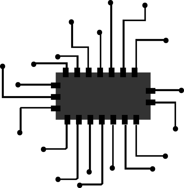
Now let’s look at designing a circuit to run the mess of cables I have shown in the last posting. The resulting circuit needs to be able to:
- Transmit an infrared signal to control the car radio. This will be accomplished by an infrared led controlled by one of my microcontroller’s pins
- Measure the resistance of a resistive ladder that is already found on the car’s existing steering wheel wiring
- Light the steering wheel controls and maybe control this lighting
- Adding to all of this I decided to have certain combinations of keys lock and unlock the car doors because there’s no comfortable button for this on the dash (it is after all a 10-year-old car that was designed in the late nighties – the Astra G was in production from 1998 to 2009 and mine is a 2007 model)
To control all of the above of course I chose the ATmega 328 microcontroller. It’s cheap, easy to use and the web is full of circuit schematics and suggestions of how to implement stuff with it.
Regarding the IR communications I found this link:
https://www.sparkfun.com/products/retired/10732
What I found interesting here is the circuit calculation in the Documents -> Schematic section. They are spot on and what I need. Even though the product is no longer available or being sold getting a 2N3904 and company was a trivial task and so was reproducing their circuit into mine. Thanks SparkFun for maintaining retired products and documentation on your website! The IR library that I decided on using is found here:
https://github.com/cyborg5/IRLib2
I will get into the details regarding the programming next time but the main point at this moment is that for the IR circuit I will be using pin 3 of the Arduino which corresponds to pin 5 of the actual chip.
Next on the list was reading the resistive ladder. To do this we need a circuit that can read the total resistance of the resulting circuit when we press a button … or when we do not press anything. Basically, if we say the whole circuit that we are measuring has one resistance Rx the problem boils down to finding or building a circuit that can read a resistor. I am not a fan of reinventing the wheel (well not in this case at least) and an ohmmeter circuit already exists here:
http://www.circuitbasics.com/arduino-ohm-meter/
So to the pin I designate to read the input I need to attach just a wire going to my controls and a resistor of a known value going to Vcc. Now Vcc of the circuit is 5V (we are on the Arduino side of the circuit). The maximum and minimum values of Rx I calculated after drawing the circuit in the reverse engineering part the total resistance varies between 82 ohms and 3674 ohms. By that I chose the known resistor to be a 1k resistor. Because the pin that will be assigned to this task will have to read an analog voltage and tell me the resulting reading I have to chose an analog pin. The lucky winner will be A0 (pin 23 on the actual chip) because …well no reason other than it’s the first of the analog pins .
Regarding turning on the steering wheel lights I need to be able to send them 12V (I am not changing anything on the existing circuit and the lights are designed to run at 12V … and they are dim as it is. Because of this I need to be able to control 12V although my Arduino is running at 5V. Furthermore, my existing circuit is already tied to a general ground so if I want to control the lights by interrupting the path to ground I will be doing this for everything that is on the steering wheel … that means the resistive ladder even the horn … this is a big NO. I need to control the positive supply which is individual. What I need is called high-side switching. And this guy here does a great job of explaining it.
https://jeelabs.org/2012/11/12/high-side-switching/
The transistors I chose are just general purpose, easy to find transistors in my area , namely BC557 and BC547, with no specific reason other than availability. This might help:
The part about Europe is spot on so if you might ever need to build something like this in other parts of the world 2N3906 and 2N3904 will work (yes, the 2N3904 above could also be a BC547, somehow, I did not take that into consideration when I got the parts). Because while thinking the circuit out it did not occur to me to check how bright the backlighting on the controls was with the plastic caps on I envisioned them having fade effects for different functions etc. This proved to be a bad idea seeing as the backlighting is completely invisible in the daytime and barely visible in the night. I am getting ahead of myself here but this is the reason why I wanted a PWM capable pin for light control, so I chose pin 11 which is pin 17 on the IC itself.
The pulses for door lock and door unlock will also be 12V 100ms signals. I hope this is the correct signal length to have the door lock controller execute the command. Because of this they will use the exact circuit as for backlight control. One will be on pin 12 and 13 just to have this circuit in triplicate one next to another. Also because lock and unlock are straight digital signals with just off and on states (represented by 0V and 12V or so I hope the existing logic works In the car) there is no need for PWM.
To get the ATmega running we need some extra stuff. The bare necessities are a 10K resistor between the reset pin (pin 1 on the IC) and Vcc, a clock source to pins 9 and 10 and power and ground to the IC itself (pins 7 and 20 for Vcc and 8 , 22 for Ground respectively). The clock circuit I will use is just the standard clock circuit found on the Arduino board. It contains a 16Mhz crystal oscillator and two 22pF ceramic capacitors that got o ground.
Equally important to get the ATmega programmed I will be inserting an extra ground pin header somewhere so I can make sure I can talk to this circuit with an normal Arduino board (IC removed) and adding a header so I can connect to the TX and RX pins (2 and 3 on the IC). Making sure there is no ground difference for the circuit and the Arduino board is only half the struggle. I should also worry to have the supply Vcc offered by my circuit’s supply module be equal to the Vcc of the Arduino board. This would most safely be done by having the Arduino supply my ATmeega chip with power while programming, but I discovered I can have them at different voltages as long as the difference isn’t too high (we are talking tenths of a volt) mostly out of need. I needed my circuit to be able to “talk” to my PC via the Arduino Uno’s serial for debugging. This is probably not safe for the pc and board but I have yet to find a better solution at this time.
The 5V supply voltage will come from an electronic module. I ordered 5 LM2596 based supply modules from china. They are compact, probably not the best in terms of isolating electrical noise and other parameters but they do work. So, I plan on using this occasion to not only profit from the small footprint that one module uses but also test how reliable it is. It will be set to 5V and I plan on supplying it from a 12V line that gets switched on when I turn the key in the ignition. No use in having the circuit run with the car off, draining the battery, plus if there is some kid of false signal triggered to close or open the doors odds are I will be behind the wheel and not somewhere else being locked out of the car or not knowing the car is unlocked. Remember failure is ALWAYS an option when you try something new, when I do it it’s almost guaranteed. As a final note once everything is built and tested I will measure the peak amps this circuit uses (I expect it to be a small value) and insert an appropriate fuse before the china power module and equally important the “me” resistive-ladder-reading-IR-emitting-control-circuit-adapter-thing.
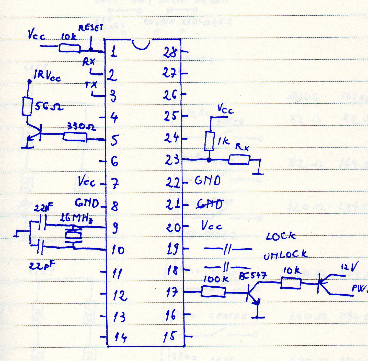
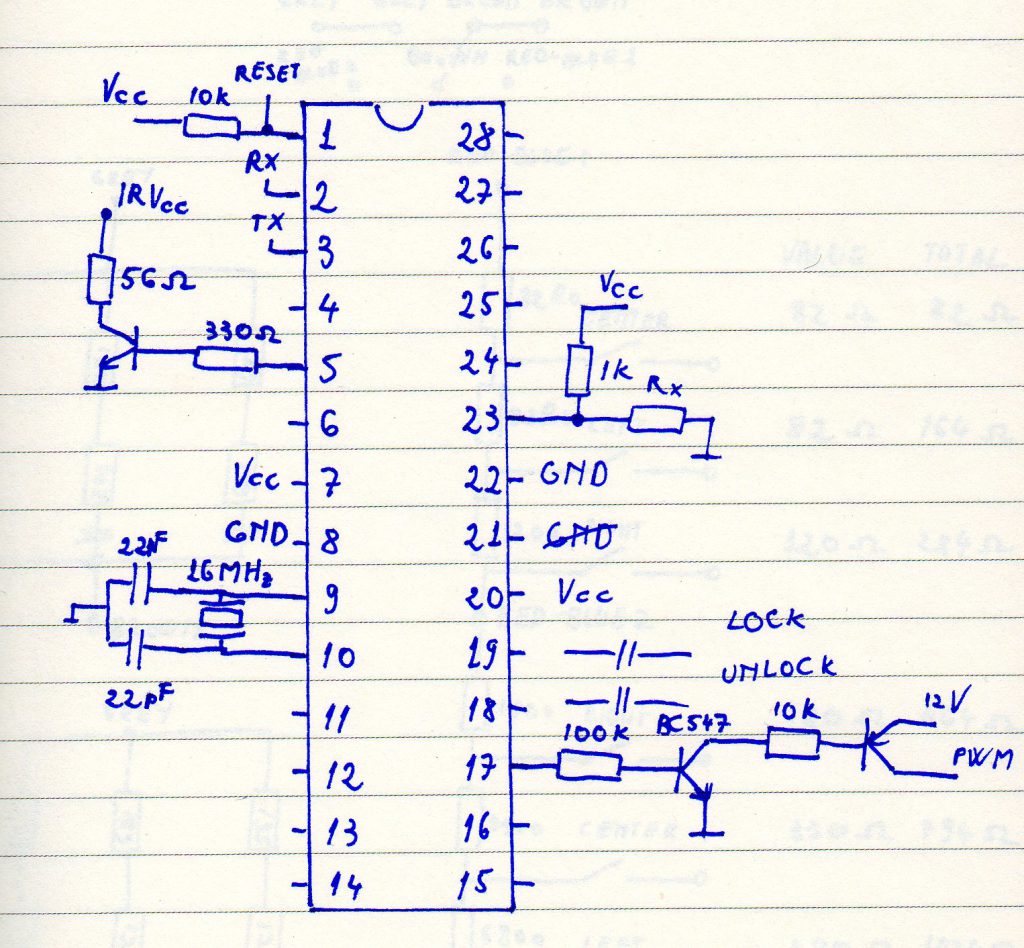
You can see all the circuit together below. And because I named every pin used by the IC for the different functionalities you can see where each functional part of the diagram is.
Also, here is the diagram of the existing circuit in the control modules that came with the steering wheel. If I ever think of a way to make it more understandable I will update it.
This took longer than I expected to write. On the flip side it also resulted in a longer article. Next time I will talk code.
Thank you very much!!!!!! 🙂