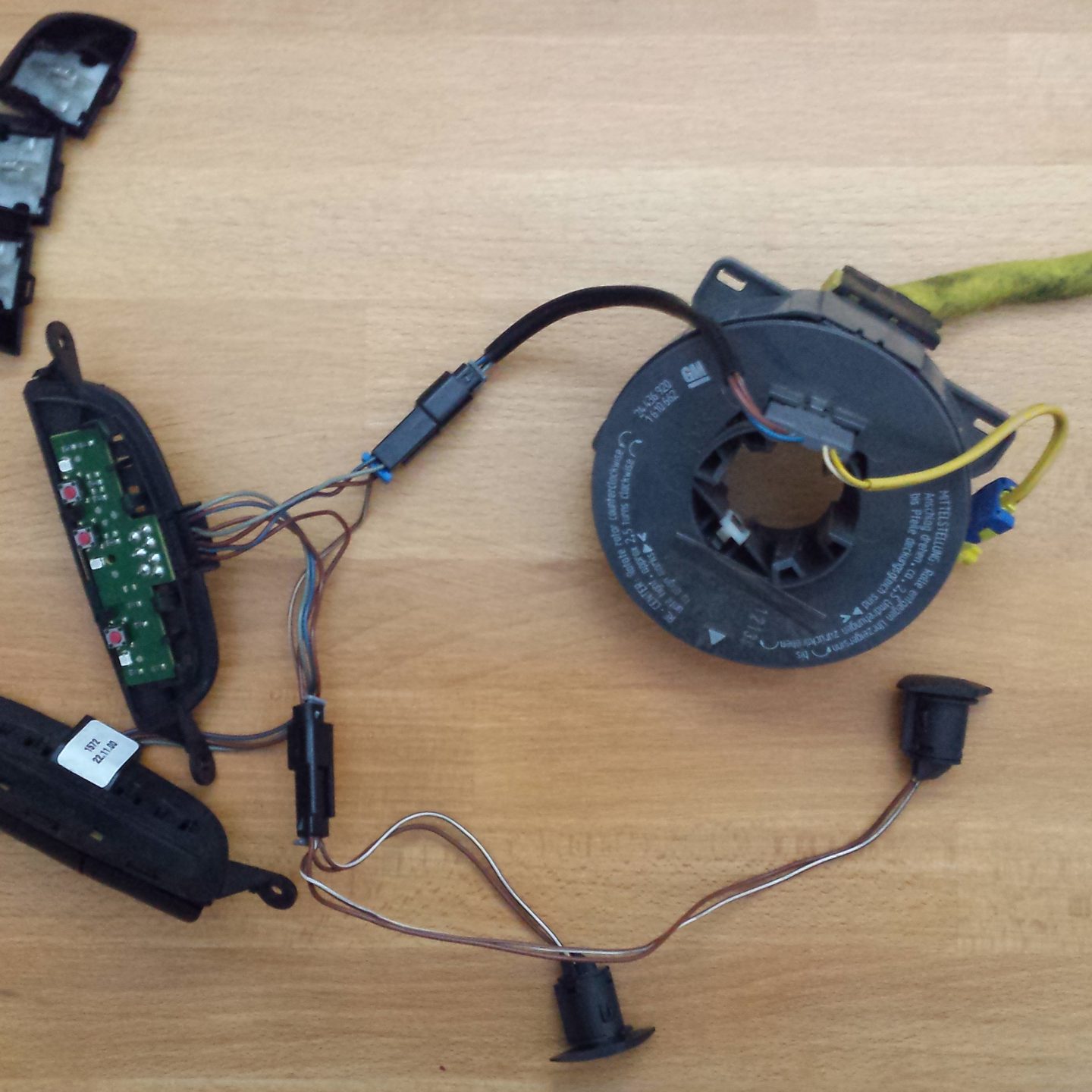
Reverse engineeringReverse engineering, the puzzle part. Well reverse engineering in the sense that I will take apart the steering wheel controls and figure out how to connect them to my circuit. After taking out the controls from the wheel I am left with the 2 rows of buttons that go on the left and right under-side of the steering wheel, horn buttons and the wiring loop with the ring that holds everything in place intact when I steer.
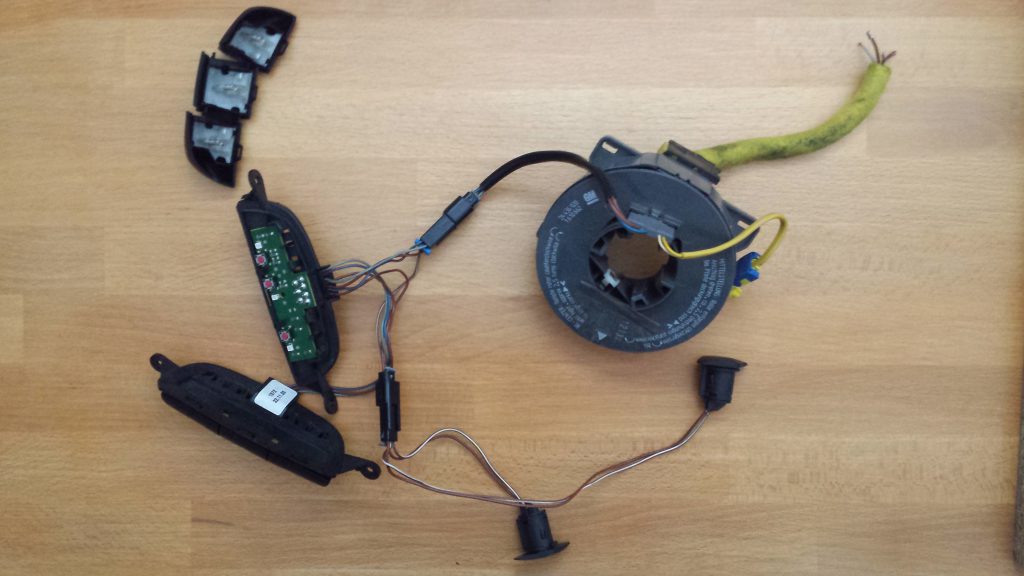
The main reason everything is still connected as you see here is that I can’t figure out how to disconnect the electrical connectors without breaking them. That being said I didn’t even give this much thought as having all the parts here help me figure out which wire that comes out of the loop (the yellow thick hose-like thing to the upper left) does what. What I managed to find out when purchasing this part at a local workshop is that the yellow wires control the airbag so I am not messing with those wires (and yes the yellow big wire has yellow small wires inside …among others). I also found out and it’s quite clear by looking at the horn buttons that the brown-white wire and the brown wire control the horn. Presuming brown is ground, this leaves us with 2 wires: grey and blue-red.
Now the 2 control modules seem to have the buttons held on by clamps. One on the exterior edge that come off easily and … I can’t see anything else holding the button on but it is staying on. Further prodding with a small screw driver showed that by inserting it into the 2 smaller orifices to the other side of every cap pushes the it off its hinge. Care must be taken to not brake these parts. Of course, I managed to brake one not by taking it apart the first time but by repeatedly assembling it and disassembling it while doing tests… crap. The correct movement seems to be to insert the screwdriver with the edge facing away from the center of the victim… ah cap… and gently but firmly push the end of the tool the other way by this prying the cap off its hinge. Anyway, taking off the button caps leaves us with this circuit:
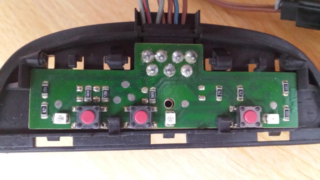
The first interesting observation if that the circuit is not completely populated. The second observation is that the circuit of the other control module is the same PCB with another configuration done by populating different parts. Neat way to save a money in production. After following the circuit with a continuity tester, I wound up with 2 separate circuits:
- A lighting circuit that gives the button caps a backlight that is between Grey and Brown
- A resistive divider that from the Blue-Red wire to ground (brown)
In the next posts I will be attaching the schematic of the control system, sharing my thoughts and considerations in designing my control system and we will wrap things up with the code that will run all this.