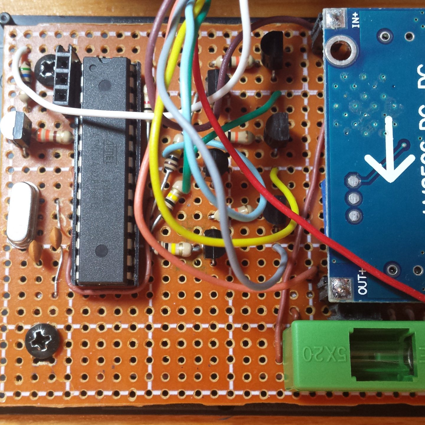
Building the module has been an interesting experience. I tried something new (at least for me) on the circuit. I didn’t talk much about the circuit used to power all of this in the other articles because I purchased an off the shelf module. To be more exact I opted to use a LM 2596 module off AliExpress ( https://www.aliexpress.com/item/Wholesale-Price-LM2596-DC-To-DC-Step-Down-Module-3A-Ajustable-Buck-Converter-Power-Supply-3/32704316040.html?spm=a2g0s.9042311.0.0.cwQfMD ) This buck transformer module Is used as a daughter board, the motherboard being the prefboard that got used for the main circuit build. In regards to the “motherboard” part of the circuit, things are pretty simple the ATmega takes center place (well to the left but you get it) with all necessary components tied around it. It gets 5V from the step-down module and 12V, where it’s necessary, directly from the car. Speaking about 12V, automotive circuits don’t have a stable 12V. The 12V line can go from anything lower all the way up to 14.5 15V if the charging circuit is having a bad day or the battery is dying. The good thing is that the little power module can work all to way to 35V.
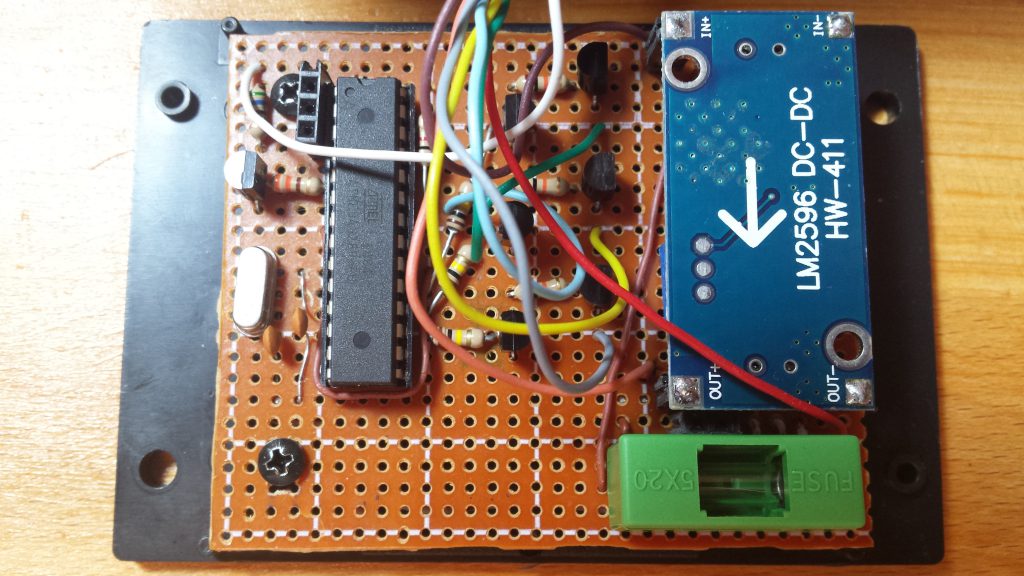
I plan to have the control module powered only when the car engine is on, I like keeping an eye on things. And I also want to use a low amperage supply line that already has a fuse in its circuit. That being said the smallest fuse my car has is 5A. My circuit takes much less than that so by the time the big one automotive fuse blows my tiny module could be half way up to magic-blue-smoke-grenade status. That does not sound pleasant, so let’s not have that happen. To avoid any unpleasant failure modes and smells in the car I have the big green thing on my circuit. The big green thing is a fuse holder. Yep the old school round fuses. A pain if you have to change one on the road but if it blows I can go without the module working no problem and sourcing low amperage automotive fuses is a pain if not impossible.
Now, the way I usually work is to build a prototype on a breadboard, program it by using Arduino boards without the Megas in them as programmers and after all the bugs (hopefully) are chased down to the pits of negligence and ignorance from where they came from the final circuit is built and tested one last time. Bottles get opened and celebrations happen. This is the plan. And like any plan it fails miserably the moment it begins. How did I fail on this one? Well in a couple of ways:
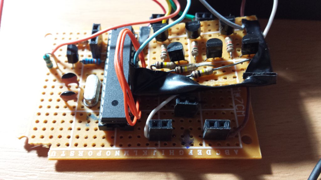
- I was so confident in the circuit I built it before proper testing was done … twice. The first one didn’t correspond to the actual needs dictated by the existing controls on the car. I glossed over this while talking about reverse engineering but the truth of the matter is you truly finish deciphering someone else’s circuit only when you use it in something and it works. Thinking you know how it works is all fine if you don’t mind finding bugs later. The second one had to be rebuilt because of what I can only assume was an accident. It worked fine on the first trials and then stopped working altogether. I recycled the ATmega from it and it continued to work fine not just in that circuit but in 2 other circuits. I could have stopped and debugged every connection but I wasn’t too happy with how I had used my space on that one. And this brought me to the third one. The third one I got right. It involved some extra testing on the breadboard beforehand but it is now in physical form and works.
- Then there’s the software. Nothing too surprising here, went through a couple of revisions to get everything working just as I wanted them. I did not bother keeping an active history of this, the only reason I went from 0.1 to 0.2 was that I changed the logic behind detecting long presses versus short ones and I felt it was a big enough change to justify it.
- One last failure (up to this point) I had was when I started the “field tests” in the car. I didn’t want to take the radio out of the car so for my development I programmed another Arduino to act as an IR receiver and tell me what signals it was getting. As it turns out somewhere along the road some misunderstanding happened in regards to what the actual codes I got represented. The way I used the extra Arduino to read the signals meant that I only caught on to this bug once I had my circuit all packed up running from a 9V battery in a box and desperately trying to send signals to my radio.
So, this bring us to this:
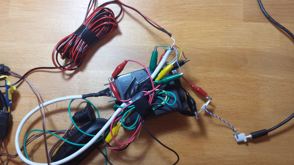
This is the module undergoing a test on my desk. It is performing well, it passed a field test on the car and a 12-hour “burn in” test on the bench, so all that’s left is to get it incorporated into the car and enjoy the road. I will be probably posting an article after using the module for a period of time probably 6 months or something so I can say how it feels and if anything else needs to be changed in a future revision. That being said if I have a good…or bad reason I will be writing sooner about it. Failure is always an option!
The complete project as of 8 February 2018:
- http://www.neo-kobo.ro/2017/11/23/project-steering-wheel-audio-controls/
- http://www.neo-kobo.ro/2018/01/11/project-steering-wheel-audio-controls-reverse-engineering/
- http://www.neo-kobo.ro/2018/01/20/project-steering-wheel-audio-controls-circuit-design/
- http://www.neo-kobo.ro/2018/01/25/project-steering-wheel-audio-controls-programming/
- http://www.neo-kobo.ro/2018/02/01/project-steering-wheel-audio-controls-programming-ii/
- http://www.neo-kobo.ro/2018/02/01/project-steering-wheel-audio-controls-conclusions