Now, after singing the praises of working with an Arduino in the first article of this series , let’s get to know some hardware basics.
ATmega328P AVR- The brain of the thing
The ATmega328P AVR microcontroller is the “brain” of the Arduino UNO. This is what you program , this is what makes the magic happen in all of your projects and this is what the Arduino board is built around. It comes mainly in two “flavors” :
- a THT – Through Hole Technology variant (the one that looks like a big black bug with metal legs sticking on its sides and also occupies a good part of the board) that is in a socket
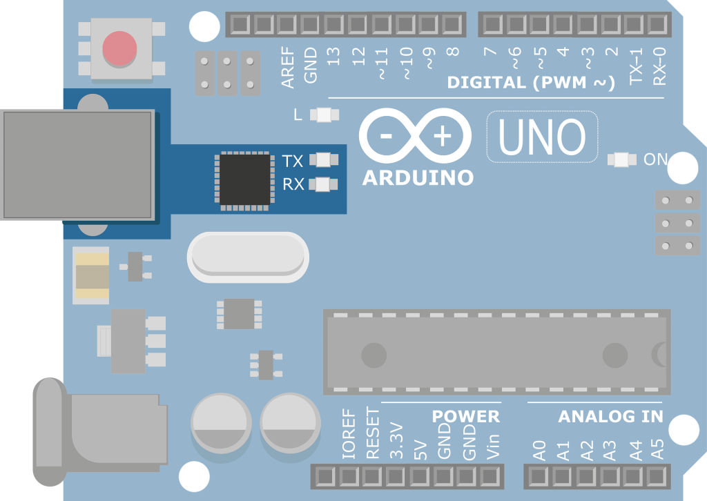
- a SMD – Surface Mount Device variant (smaller and decidedly harder to solder by hand, not to mention not in a socket, and it also makes the board look empty)

Arduino UNO SMD version -Wikimedia Commons

The reason that I expressly specify that the THT variant is socketed is that you can have a THT chip directly soldered to a board. The fact that the Arduino has the microcontroller socketed allows us to change the chip if we need it. Also and more importantly it allows us to program a chip and move it to the final circuit where we want to use it…pretty handy.
Now , we know where the Atmega chip is located let’s see what it can do.
ATmel ATmega328P AVR – general specifications
Firstly let’s get something out of the way so people don’t get confused:
- Microchip is the company that builds this chip.
- AVR is the family of microcontrollers created by Microchip that have easily reprogrammable flash memory (as opposed to chips that can be programmed once and then have that programming for the rest of their functional life and chips that had other forms of reprogrammable memory).
- ATmega is a subfamily of these chips that have about 2 to 256 KB of memory. The official name of these is megaAVR but because most chip designations start with ATmega the latter name stuck.
Naming out of the way let’s get back to the problem at hand : the specifications
Inside both the THT and SMD variants there’s the same small silicon die. A silicon die is a piece of silicon that has extremely small circuitry etched into it. This is all the circuitry of a microcontroller. The plastic packaging is just that: packaging and protection for the silicon die. You could just brake in them and you can see the die , but there’s no need. As with every idea on the internet , somebody has done it already :
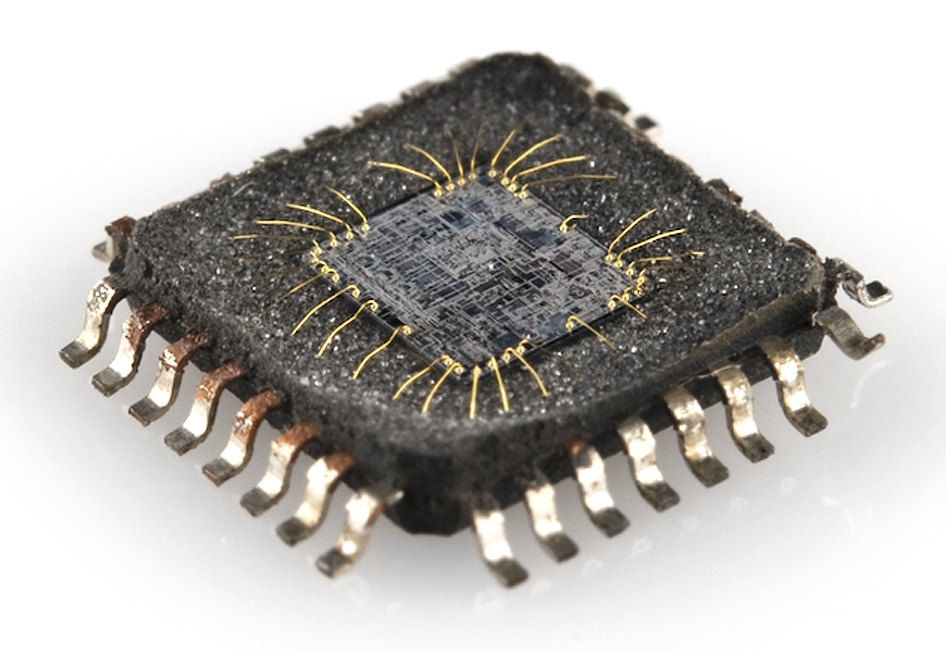
The golden wires you see going from the die are going to the outside world : they connect to the pins we see on the package. So all 328 chips have the same wafer (die) therefore he same specifications :
- Harvard 8-bit RISC Architecture
- 32K program memory (of which about 1k is used by the bootloader… you need that bootloader leave it alone for the time being)
- 2K SRAM ( yes 2K 2048 bytes …16384 ones and zeroes … if you come from a programming background you will start thinking a hole lot more about every variable you declare)
- 1K EEPROM memory ( EEPROM memory is good for about 100.000 write cycles but can’t be read any number of times so using it as extra SRAM is a big NOPE but it’s great for storing constants and any other data you only need read when the program executes)
- 20MHz Max Frequency ( Arduino uses 16Mhz)
If these specifications get you down don’t worry. Arduinos are not meant to be powerhouse machines but these stats are usually more than enough to get the job done. That being said, people have done amazing things with the Arduino UNO and there are always other “flavors” of Arduino in case you need more power.
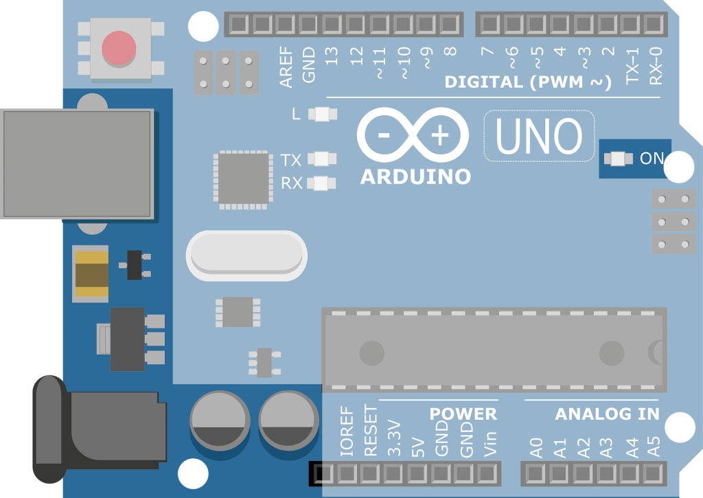
Now that we have a basic grasp of the UNO’s main component, let’s see what else is on the prototyping board to facilitate us using the microcontroller to its full potential.
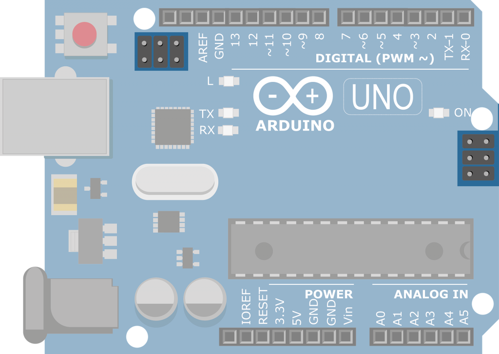
Arduino UNO-hardware layout
So, what exactly do we need to make a microcontroller function ?
- Well we need power. In the case of the Arduino UNO that comes in two forms.
We get power by simply connecting the Arduino to the computer by USB. This usually gives us about 500mA of 5V power. The ATmega chip runs at anything between 1.8v and 5.5V. So 5V is great for the UNO.
The second way of getting power to the Arduino is by a DC power plug. This is a 2.1mm barrel plug wired as a center positive. This connection can take 7 to 12V power. Now you may be thinking : ” If the ATmega chip can run at anything between 1.8V to 5.5V why would it need 7 to 12V here ? “. Firstly the 328 microcontroller needs about 5V to run at full speed so the designers of the Arduino wisely decided to have the board give it that voltage level. Secondly because they don’t expect any specific voltage on this input there’s a power regulator that outputs 5V to the Arduino. As a rule of thumb with any power regulating chip the input should be 2V higher than the expected output.
Alseo, when the board has power there is a power LED that lights up.
- We also need a way to program the microcontroller – a communication interface.
Therefore we need a way for the computer to communicate by serial USB with the microcontroller. While programming the chip is the bootloader’s responsibility getting the actual data from your PC to the ATmega 328 is the USB to SerialIC chip’s job.This chip used to be a specialised FTDI chip (and FTDI drivers are still available) but has since been replaced by ATmega 8U2 or 16U2 chips. This chips convert the data received by the Arduino into data that can be passed into the microcontroller’s UART pins allowing it to be programmed.
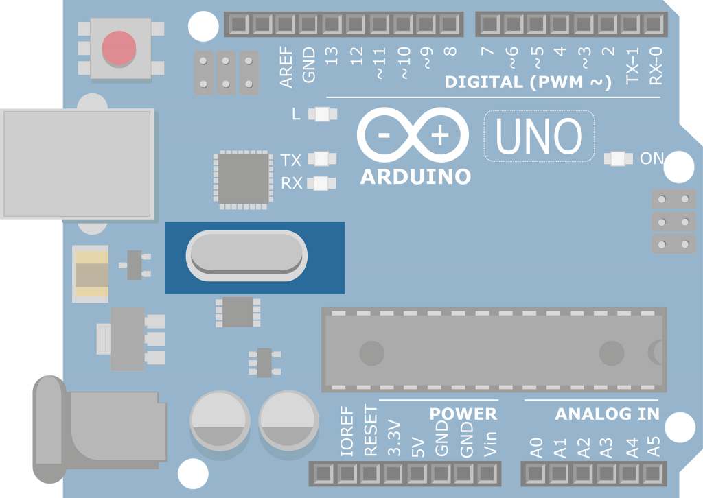
- With power and communication sorted we still have to make sure there’s a clock involved to get everything in sync.
The Atmega 328P can run without one by using the internal clock. This is somewhat imprecise and has some drawbacks. One of them is that you can only communicate with the Arduino by using a lower baude rate (uploading sketches will take longer etc). this is why the Prototyping board has a clock circuit with a crystal oscillator.
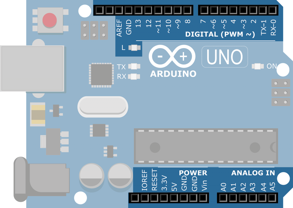
- So now we have the ATmega 328 powered , it can communicate with the PC and be programmed , everything is running in sync with a good clock so what are we missing ? Inputs and outputs !
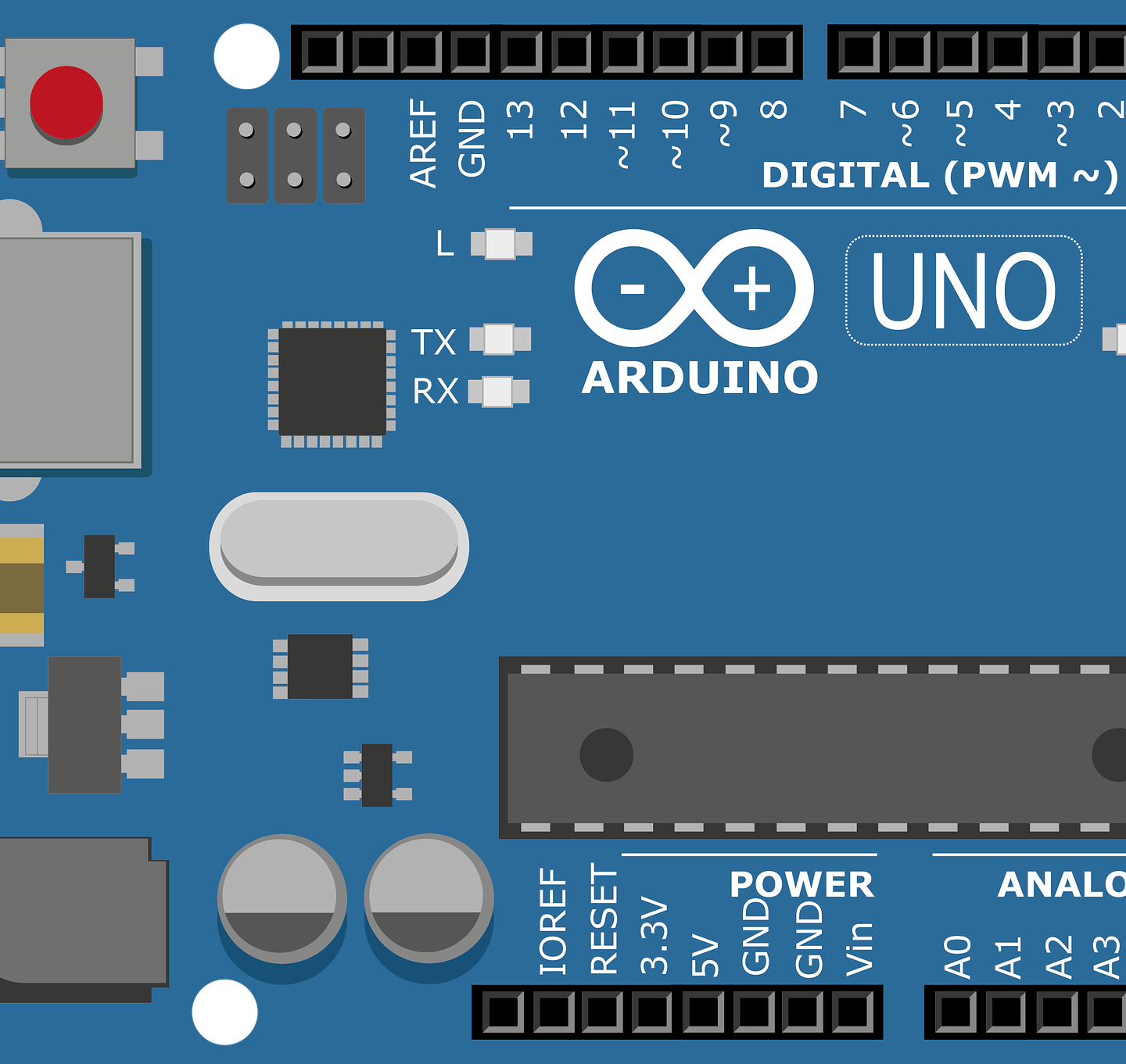
Without those the microcontroller board is completely useless to us. The inputs and outputs situated on the exterior of the board allow our Arduino UNO to react to the environment and control stuff in that environment. The inputs and outputs are marked 0-13 and A0-A5. Some of the 0-13 are also marked with a “`” symbol.
The 0-13 pins are called Digital General-Purpose Input/output pins (Digital GPIO) These pins can either receive or emit a state of HIGH(5V) or LOW (0V). This is useful for a lot of things like turning a led on or off or finding out if a part of a circuit is powered etc). A select few pins can also do what is called Pulse Width Modulation or PWM. In the shortest description possible this means turning a pin high and low so fast that it behaves like a analog pin. These pins are marked with a “~” symbol. Pins 0 and 1 are usually used for serial communication with the PC but can be used for other roles (they are marked with RX for Receive and TX for Transmit and have leds tied to them to indicate data transfers). Pin 13 also has a led tied to it so when you set pin 13 as HIGH this led lights up.
The Analog pins ( A0-A5) can function both as analog inputs and digital inputs/outputs. That means that they can read values between Low and High. This is done with the help of an internal Analog to Digital Converter (ADC). For example this is useful if you want to read the level of water in a reservoir. And as a bonus these pins can function as normal digital in/out pins, rolex replica watches which is useful when you run out of those on a project and do not need the analog functionality of the pins.
Other pins present are extra 5V and 3.3V outputs that can be used to power external electronics in our projects as well as the ARefIORef and reset pins. The Ref pins are used to adjust reference voltages in some cases and the reset pin is connected to the reset pin of the Atmega chip.
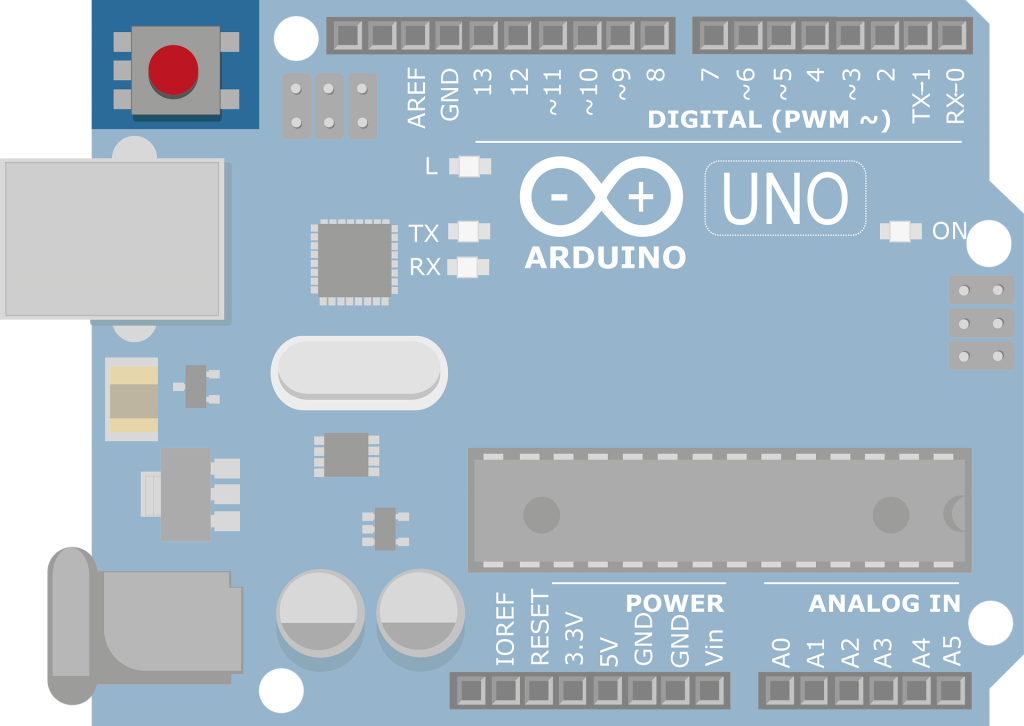
- A way to reset the hardware and software. The reset button
The Arduino UNO resets everything when it is being programmed and if it was running already , when you connect it via USB to the PC. Any other manual resets for those moment when nothing seems to work are handled by this button. ( The “Have you tried turning it off and on again?” moments )
- One last feature on the Arduino Board witch is not absolutely necessary but nice to have is the presence of 2 ICSP headers. This can be used to program both the 8/16U2 ATmega used for USB to serial conversions and the ATmega 328.
And this about wraps it up for the Arduino UNO hardware. Now that I bored you with the hardware I can talk about the software side of stuff in my next article.