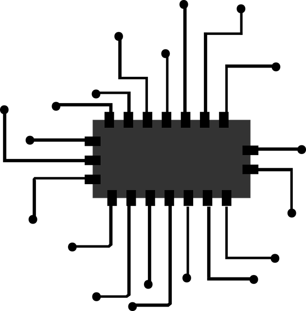
Let’s first concentrate on how we can influence the outside world with our Arduino. If we want to control something, to signal something or output some information, everything is done by using output pins. The output pins are 13 digital pins and 5 analog ones in special cases.
Digital outputs
The digital pins can be used as outputs by declaring in the setup the pinMode for that respective pin.
pinMode(13, OUTPUT);
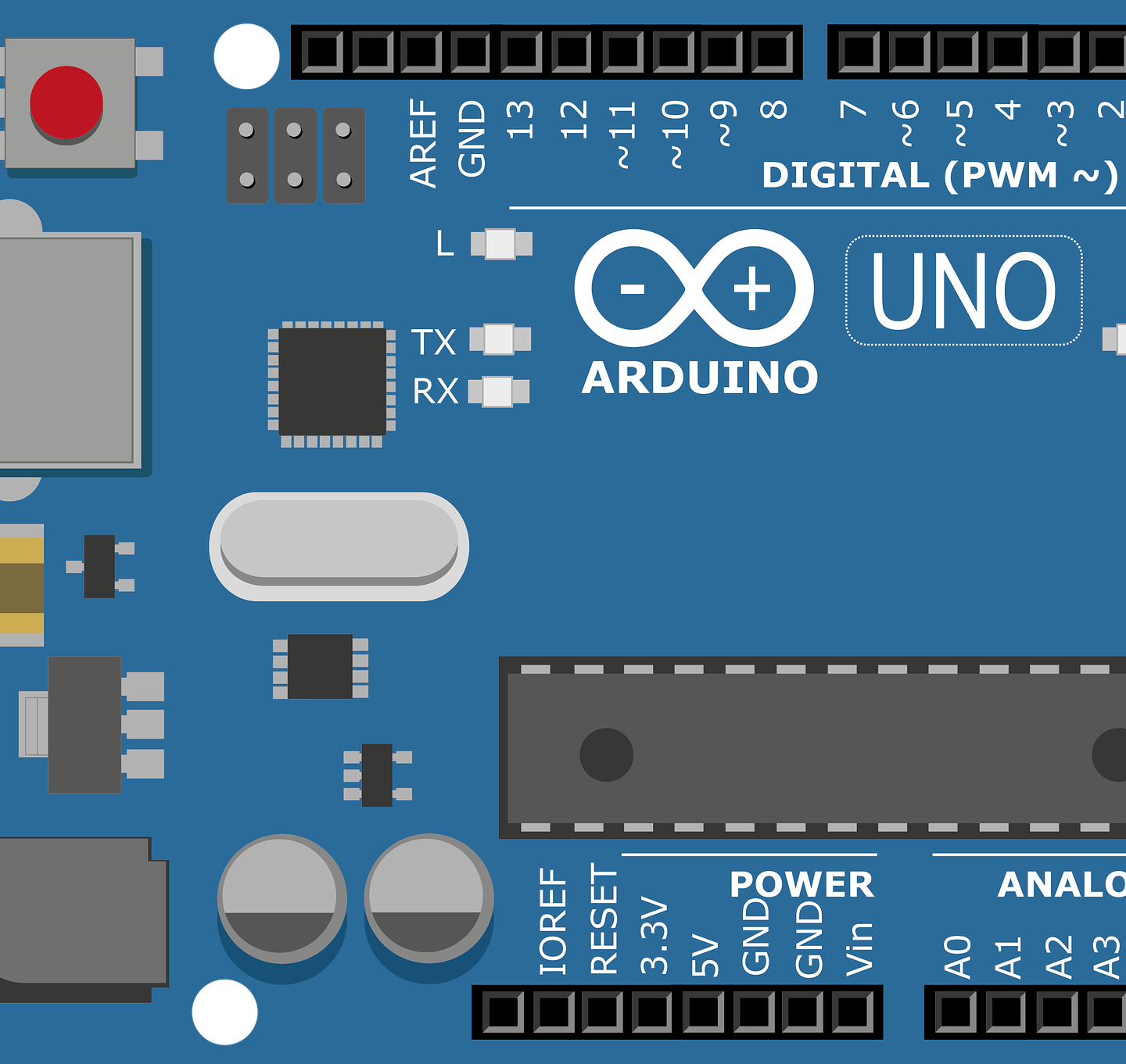
This sets pin number 13 as an output. For an Arduino UNO board the pins that can be used as digital outputs are pins 0-13 (all the digital pins) as well as the analog pins (A0-A5).
OK we have a pin defined as an output.. whoop de doo . Let’s see how we can do something with it. Digital outputs have two states : HIGH and LOW…or On and Off … or 1 and 0 depending on what you prefer. The HIGH or 1 translates to the voltage at which the ATmega328P is running at. In our case ~5V. And LOW or 0 is …well 0V or Ground reference voltage.
To get these values you have to write to the pin with digitalWrite:
  digitalWrite(13, LOW);
  digitalWrite(13, HIGH);
So this is it for Digital outputs. I was planning on continuing with analog outputs but that means I will have to write an electronics basics series and discuss among other things PWM…well, rolex replica watches in for a penny, in for a pound.
“Analog outputs”
The Arduino UNO and more exactly the the ATmega microcontroller does not have analog outputs. this would require a DAC ( Digital-Analog Converter) which is absent from the chip. Arduino however has a analogWrite(pin, value) function. The analog write function uses the PWM functionality of the digital pins marked with the “~” symbol. The pin variable is as until now the pin we are referring to (pins 3, 5, 6, 9, 10 and 11 have PWM) and the value refers to the duty cycle (more on this in the PWM article).The range for value is from 0-off to 255-on.
analogWrite(11, 125);
Let’s look at a practical example now:
void setup() {
 pinMode(LED_BUILTIN, OUTPUT);  //initialize digital pin LED_BUILTIN as an output. LED_BUILTIN is set to the correct LED pin independent of which board is used. Another option would have been pinMode(13, OUTPUT);
}
// the loop function runs over and over again forever
void loop() {
  digitalWrite(LED_BUILTIN, HIGH);   // turn the LED on (HIGH is the voltage level 5V)
  delay(1000);                       // wait for a second
  digitalWrite(LED_BUILTIN, LOW);    // turn the LED off by making the voltage LOW
  delay(1000);                       // wait for a second
}
All this program does is blink the onboard led that is connected to pin 13 on and off every second. The example is also found in the File -> Examples -> 01.Basics -> Blink and is also generally used to check that the Arduino board and environment are configured and running properly.
So here we have it , all about the Arduino UNO outputs.
Next time expect a small post about electronics basics and when that’s done I’ll get on with inputs