
Let’s have a little discussion about electrical signals and waveforms.
In electronics we usually want to understand how something works and that usually starts with understanding what the electricity in the circuit is doing. If we have a constant voltage it’s simple. We have a 9V voltage source, every time we measure it we expect about 9 volts if the power supply is any good. The problem gets somewhat complicated when we have logic circuits. They don’t get too complicated, any pin that is a digital output will either be a logical 0 which is ground voltage (0V) or a logical 0 which is the voltage at which the microcontroller or chip runs. We just have to consider that there are 2 states of that point in the circuit. But what do we do with analog circuitry? Analog signals that pass through can have a whole range of voltages, that’s the point of the circuit being analog. Radio reception, old analog tv signals, circuits that use modulation, audio amplifiers, or in the very least PVM circuitry, they all have a waveform that is a little more complex than just the odd on and off, high or low.
And all those electrons dancing around there can be confusing. We started by analyzing a single point in the circuit and finding a voltage. Then we introduced the notion of time in the equation. We had logic circuits that could be either high or low depending on what moment it was. And in analog circuitry we give time a whole lot more respect. Thing we are looking for is to find out what value the voltage has at a specific point in a specific period of time. The keywords here are voltage and time. If we want to plot that on let’s say a graph you would have voltage on the vertical axis and time on the horizontal. This means that as you move from the left of the right you go forward in time and can see what voltage there’s at that point in the circuit in that point in time. Simple enough? Let’s look on an image on my oscilloscope: (don’t worry I will explain what that equipment is another time)

Does not look very useful does it? … no? Well that’s because What you see here is just noise. Any electrical signal can be displayed like this so there you can see some electrical noise when I just visualized the signal off my desk lamp. Yes, I literally measured the voltage on the metal case of my desk lamp. So, this is just a mess, nothing repeats itself, there are no rules nothing … just noise. What is interesting to discuss is periodical signals, rolex replica watches signals that change in the same way in every section of time if you split the time axis into equal sections. They look like this:

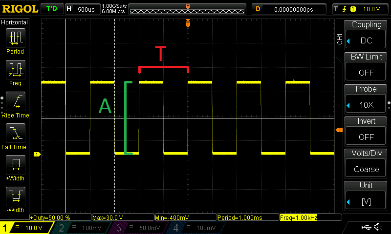
Much better no? (that’s my scope’s test pattern) It’s what’s called a rectangular wave signal and I think you can guess the reason. Other standard signals are triangular, sawtooth and sine wave. I will ignore for now the characteristics of these signals and just concentrate on the more important general characteristics of periodic signals. These are:
Period (T)
The period is the one smallest complete element that repeats periodically, it is measured in seconds (with different scales, usually very low in electronics)
Frequency (f)
F=1/T
This is measured in Hertz. This is basically how many times the given period is repeated in a time interval ( a second ) 1 hertz being one repetition per second , 1Khz being 1000 repetitions of the period in one second etc.
Amplitude (A)
The value of a point of the waveform in relation to the Y axis at any moment. It can be both positive and negative. This is measured in volts
And these are the bare basic minimal essentials regarding waveform. I will only go into detail if ever I feel there’s a need for it, I’m not much into analog circuitry and my projects are lacking in the analog department (famous last words, right?)