We had a look at how the Arduino board can influence the exterior world but that would be incomplete without a look on how the board can accept inputs from said world.
Digital inputs
In the same way we saw while using them as outputs, the GPIO (General purpose input / output) pins can be used (as the name suggests) as inputs. To do this we have to first declare them like this:
pinMode(13, INPUT);
Now that we have declared them as inputs we can at any time interrogate them to find out their state. This is done very simply like this:
buttonPressed = digitalRead(13);
One thing to remember with any inputs is that they can be damaged if the pin is exposed to a voltage greater than the supply voltage of the chip, so care must be taken in regards to this. The ATmega 328P has internal protection diodes but it’s best not to rely at all on them as they are a last-ditch defense against the chip being irreparably damaged.
Analog inputs
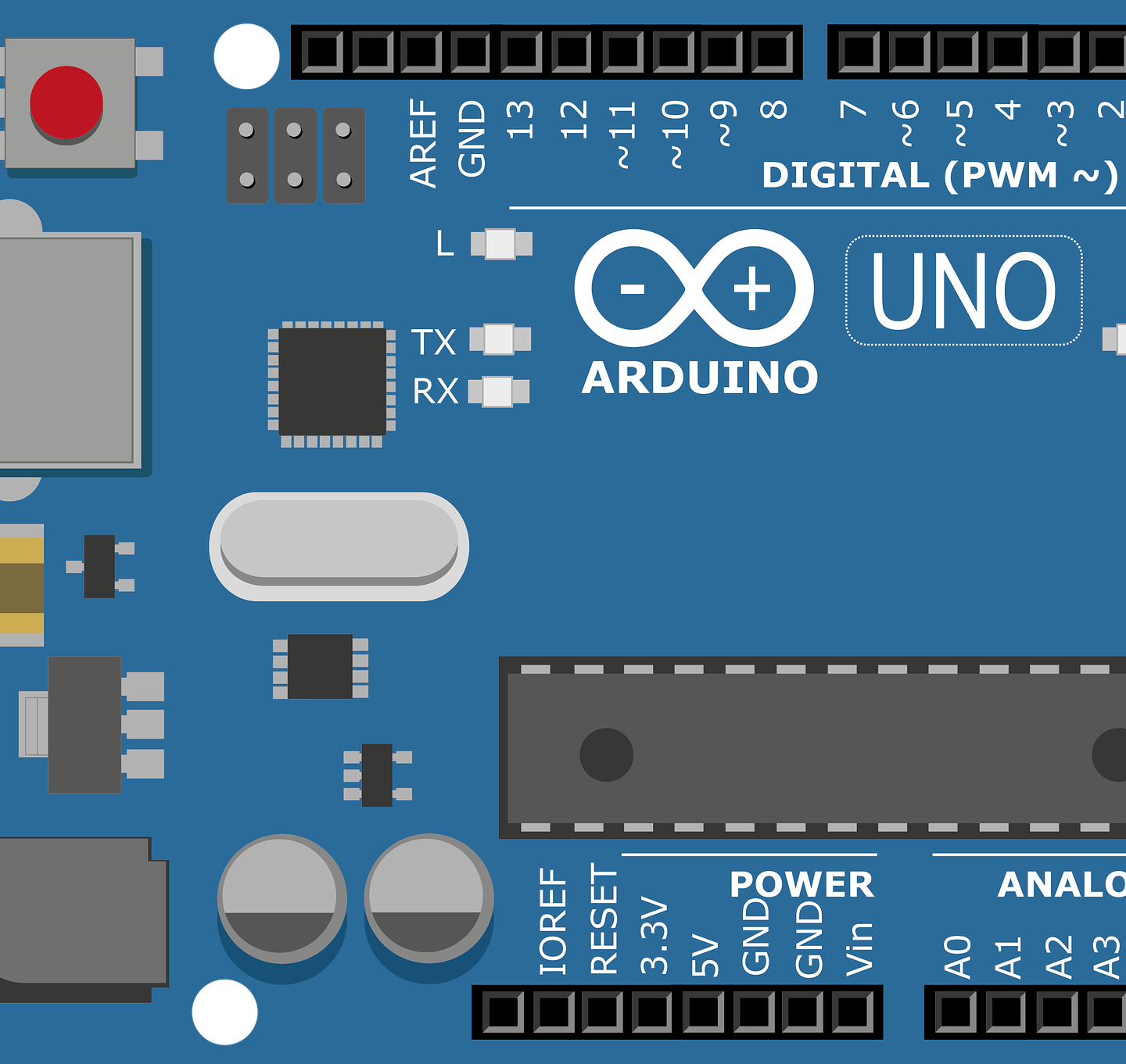
More interesting than digital inputs are analog inputs. These pins (A0 through A6) run through an ADC. An ADC (analog digital convertor) does exactly what is says on the tin. It takes an analog signal (again one that has its maximum value lower or equal to the voltage at which the IC runs at) and converts it to a number directly proportional to the voltage detected. The ADC is a 10-bit chip so it can output a maximum value of 2 to the power of ten. That’s 1024 values. Taking into consideration that it can output values starting with 0 we can deduce that the maximum value is 1023. So, if the pin where receiving 5V the output would be 1023. 2.5V and we would get half that, roughly 512. Zero volts on the input would read as 0. And regarding reading the value this is how you do it:
analogRead(A0)
Once again simple, right? you can store the result in a variable and use it later on
One other thing to consider is that these conversions take time. It usually takes 100 microseconds to have a analogRead call return the result. Not something important if you plan on reading a sensor once a minute or something but there are countless applications for the Arduino and for some this is important.
Now that you know how to use inputs there’s one more thing to take into account. You already know not to have an input pin at a higher voltage than the Arduino is running at. Another important fact is to not have “floating” pins. These are pins that are inputs but have nothing connected onto them. These pins can read wildly random values when applied a read function. This is where we use pullup and pulldown resistors.
Pullup and pulldown resistors
Let’s take the following simple scenario. Our Arduino has a button as an input. A button is a brake in a circuit when it is not pressed. Therefore, while the button is not pressed the pin is “floating” and calling any read function will not give us any useful information. If anything is waiting on this input we may get false readings saying that the button is pressed and that would trigger whatever was waiting for this event.
For this circuit to work we need a pullup or a pulldown resistor. These are high value resistors that tie the pin to ground or to V+ (V+ is just another general way to say the voltage at which the circuit is running, so usually 5V or in some cases 3.3V) if the pin is not connected via the switch to something else. How do we know if we need a pullup or pulldown resistor? Well for starters if at any time in the circuit is on there’s the slightest chance that the pin will not be connected to a voltage or ground (0v) then we need one. How do we choose between the too? Well that’s simple. In the example with a button if the other end of the button is tied to 5V and we expect, when the button is pressed, to get a “high” value when applying a read function, we need a pulldown resistor when the button is not pressed. The pulldown resistor ties the pin to ground but does not tie the 5V directly to ground when the button is pressed. This images should help:


The opposite is true for a pullup resistor. When the button is not pressed the pin is tied by the pullup resistor to 5V. When the button is pressed the 5V go through the resistor and down to ground. The resistor prevents a short circuit when the button is pressed which is very very important and also gives us a stable voltage when it is not, so the pin does not float. A common value for these resistors is 1k but this is not set in stone.
And now you know how to use inputs. You can even connect buttons to the circuit by using pullup or pulldown resistors. There’s a lot of fun to be had with just this knowledge.